



Time to read: 12 min
For engineers designing complex machined parts, the advantages of moving from 3-axis to 5-axis machining are well understood. The most capable higher-axis configurations— including 6-axis machining centers, turn-mill platforms, 9-axis and 12-axis cells, and Swiss-type turning—are less clearly defined and often poorly understood by engineers who haven’t worked with them directly.
This article explains what each configuration beyond 5-axis adds, the part geometries and applications each serves, and when the cost premium is genuinely justified vs. when 3- or 5-axis is sufficient.
Key Takeaways
- Axis count above 6 is usually additive across multiple spindles and turrets in one cell, not a single tool head coordinating that many axes at once. For design decisions, what matters is functional capability and setup count, not the raw number.
- True 6-axis machining earns its cost premium mainly on extreme-undercut geometries (blisks, aggressive turbine airfoils, optical surfaces) where surface-normal tool control is a functional requirement, not just a convenience.
- Turn-mill and mill-turn platforms eliminate re-fixturing between turning and milling operations, which matters most for parts needing high concentricity between turned and milled features.
- Swiss-type turning is the right call for small-diameter, high length-to-diameter parts where deflection control is critical, provided the design can run in a single feed-through cycle.
- Every design decision should tie back to one rule: parts benefiting from fewer setups (tight positional tolerances, complex datum relationships) justify the multi-axis premium; parts that can be simplified for 3-axis production without losing function should be simplified.
Beyond 5-Axis CNC: What the Additional Axes Actually Do
In CNC machining, an “axis” refers to a direction of either linear motion (X, Y, Z) or rotary motion (A, B, C around the x, y, and z directions, respectively). Axis counts above 5 are often loosely referred to as the sum of possible axes, including those from multiple turrets and spindles, which can be confusing.
For example, the term “12‑axis” machine usually refers to a multi‑spindle or mill-and-turn configuration whose stations add up to twelve axes—not a machine coordinating twelve axes in a single toolpath. The practical distinction that matters is not axis count but overall functional capability and how many distinct setups are required to produce a given geometry.
6-Axis Machining Centers
One common configuration is a 6-axis machining center that adds a third rotary axis to the two found in a 5-axis machine. The additional rotary axis lets the controller choose among multiple solutions for a given tool path, avoiding operating at the limits of joint travel, axis-reversal slowdowns, and singularities where two rotary axes align and lock. The result is smoother continuous-path motion, leading to better surface finish on deep contours, extended reach, and more stable control of tooling angles in a single setup.
Part geometries that justify true 6-axis include impellers and blisks with aggressive blade undercuts, complex turbine airfoils, surgical instrument profiles with compound curves, and precision optical components where surface-normal tracking requires full 6-degree-of-freedom (DOF) tool control.
Turn-Mill and Mill-Turn Centers (Multitasking Machines)
Turn-mill and mill-turn machining are terms that are sometimes used interchangeably by machine builders. Although turn-mill may commonly refer to a turning-focused platform with milling capability, while mill-turn refers to a milling-focused platform with turning capability.
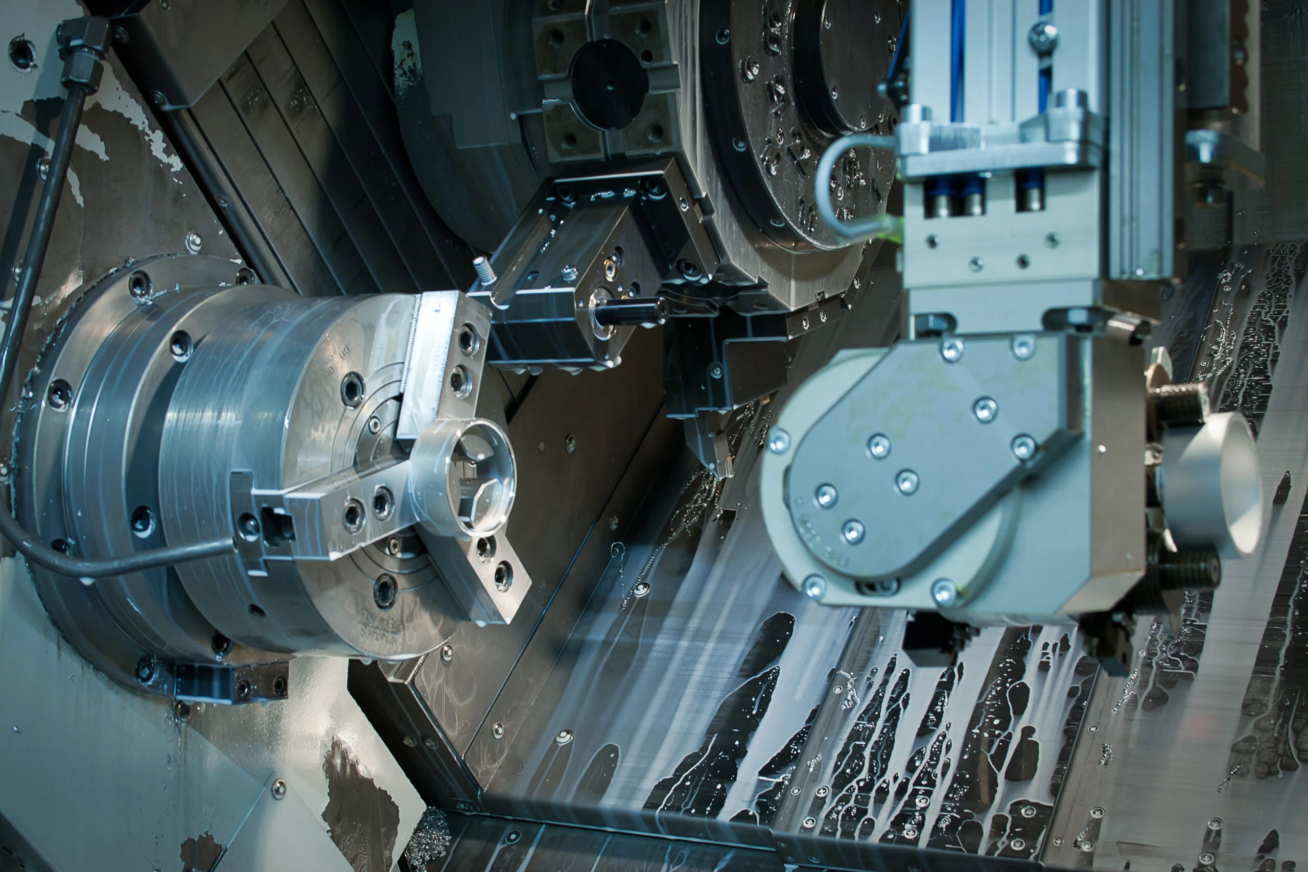
A turn-mill center combines a CNC turning platform (rotating workpiece, non-rotating tool) with milling capability (rotating tool, fixed or live workpiece) in a single machine. In either case, a part can be turned, milled, drilled, and threaded in one setup, eliminating the transfer, re-fixturing, and datum re-establishment that multiple setups require.
Typical turn-mill platforms are described as 5-axis, 6-axis, or 9-axis depending on the combination of linear (X/Y/Z), rotary (C-axis on the spindle, B-axis on the turret), and sub-spindle axes. Complex rotational parts with off-axis features such as cross-holes, flats, milled slots, and eccentric turned diameters benefit most, particularly parts requiring high concentricity between turned and milled features.
Turn-mill centers can run in two modes. Bar-fed operations machine parts from continuous stock and suit smaller-diameter rotational parts in volume production, while chuck work loads individual blanks or near-net-shape preforms for larger or more complex geometries. This choice affects maximum part diameter, material form, and setup time, so confirm which mode your part suits before specifying turn-mill. Large-diameter parts with no viable bar-feed path are often better served by separate turning and milling operations.
Parts designed for turn-mill should make full use of the advantages of the single-setup capability, locating all critical datums on the same surface that the tooling holds, minimize features requiring extensive C-axis indexing or deep backwork. The sub-spindle is also less powerful than the main spindle, limiting heavy backwork removal. Group similar operations, minimize indexing events, and consider relocating or eliminating features that push the machine beyond its efficient operating range.
9-Axis and 12-Axis CNC Configurations
The nine axes comprise the primary spindle C-axis, the sub-spindle C-axis, two turrets, each with X/Z linear and Y axes, and the live tooling B-axis. The axis count is additive across multiple spindles and axes in a cell, not nine independent axes on a single cutting head. This enables complete machining of complex rotational parts, including backworking, in a single clamping operation.
A 12-axis configuration is typically a multi-axis turn-mill with additional synchronized machining capability, or a dual-turret platform with extended live tooling axes. It is common in high-precision, high-volume production of complex small parts such as medical implants, fuel system components, and precision fasteners. The practical benefit is primarily cycle time, datum consistency, and work-in-process reduction.
Swiss-Type CNC Turning
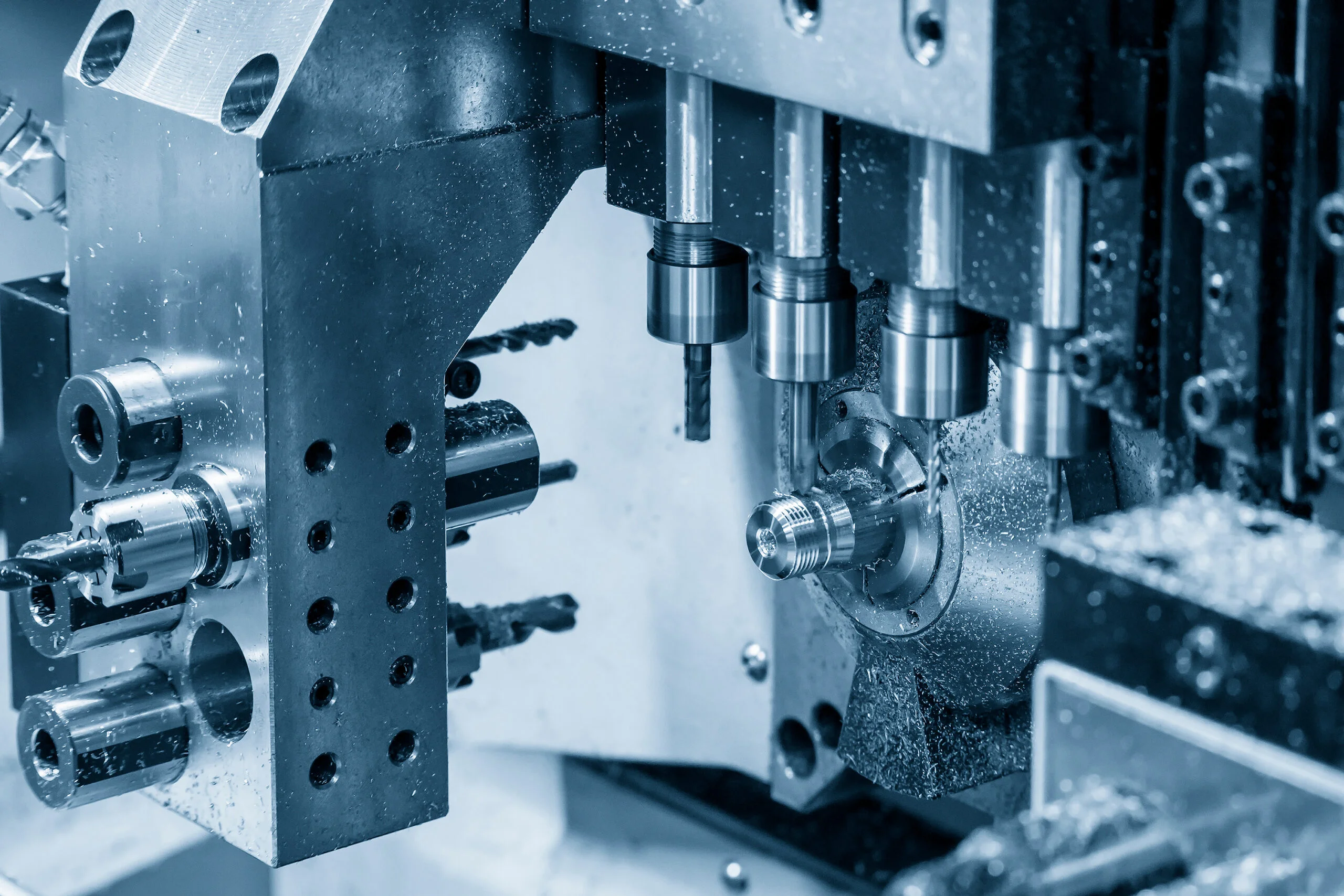
The defining feature of a Swiss-type CNC turning machine is the presence of a guide bushing positioned very close to the cutting zone. The guide bushing minimizes the length of unsupported bar stock being worked, which reduces deflection and vibration in the workpiece, enabling the Swiss machining process to hold tight tolerances on parts with high length-to-diameter ratios.
Live tooling on multiple axes enables cross-drilling, cross-milling, slotting, and threading to be performed in the same cycle. Many modern Swiss machines have a second spindle that holds the part before it’s cut free, so the back end can be machined precisely as well.
Swiss-type machining is the process of choice for small-diameter parts, typically under 32 mm, with high length-to-diameter ratios and demanding tolerance requirements. Typical applications include bone screws and orthopedic implants in the medical field, fuel injector components in the aerospace and automotive industries, precision shaft assemblies, watch components, and medical tubing connectors.
To leverage the full potential of the Swiss process, parts should be designed for a single feed-through cycle. Features that require the part to be removed from the guide bushing and re-chucked add significant setup cost and should be avoided.
CNC Configuration Comparison and Decision Guide
| Configuration | What it adds over 5-axis | Best-fit part geometry | Typical industries | Cost premium over 3-axis |
| Simultaneous 5-axis | Continuous 5-DOF tool motion; complex surface contouring in one setup | Impellers, molds, complex contoured surfaces | Aerospace, medical, mold & die | High |
| 6-axis machining | Second rotary axis on tool head; extreme undercut and surface-normal access | Blisks, aggressive turbine airfoils, optical surfaces | Aerospace, defense, precision optics | Very high |
| Turn-mill (5–9 axis) | Turning + milling in one setup; eliminates datum transfer between operations | Complex rotational parts with off-axis features | All precision industries | High |
| 9–12 axis turn-mill | Dual spindle/turret; complete part in one clamping step, including backwork | High-complexity rotational parts requiring full machining | Medical, aerospace, precision industrial | Very high |
| Swiss turning | Machining of parts with L/D ratios >10:1 with minimal deflection;Tighter tolerances for cylindrical features | Bone screws, shafts, injectors, small precision components | Medical, dental, automotive fuel systems | High |
Design Rules for Multi-Axis CNC Parts
The following design rules for multi-axis CNC parts should be considered:
Feature Accessibility
Verify tool access before freezing the design. Model the complete workpiece together with its fixturing and simulate the tool paths for every feature that must be machined in a single setup. Run collision detection to confirm that all cutting tools can reach their target surfaces without interference from the fixturing or the workpiece itself. If a feature is inaccessible, consider modifying the geometry. Adjust the fixturing strategy, or reposition the feature to a face that the machine can reach.
Tolerance Callouts on Compound Surfaces
For multi-axis-machined compound contour features, regardless of whether the machine has 6, 9, or 12 axes, the Profile of a Surface is the correct GD&T callout.
Datum Strategy
Designate the primary datum as the feature the machine holds during the full machining cycle. Each new setup establishes a fresh datum relative to the previous one, introducing cumulative alignment error. By designing the part to be completed in one clamping and referencing, all critical tolerance relationships back to the same holding feature, you preserve the accuracy advantage that justifies the investment in multi-axis capability.
Wall Thickness on Turn-Mill Parts
Thin-walled features are vulnerable to deflection and chatter in turn-mill operations due to significant cutting forces from both turning and milling passes, with highest risk when finish-machining thin walls in the same cycle as heavy roughing. The recommended approach is to rough machine the feature while the wall is still thick and rigid, leaving stock, then finish machine the thin wall with light, controlled cuts. As a practical design limit, Fictiv’s minimum wall thickness is 0.25 mm for metals and 0.50 mm for plastics. Below this, walls will not withstand manufacturing forces; if your design requires thinner walls, consider alternative processes such as electrical discharge machining (EDM, which imposes no cutting forces) or post-machining operations like grinding.
Surface Finish on Multi-Axis Parts
For functional surfaces (sealing faces, bearing seats), specify the surface roughness requirement (Ra) and note whether it is intended to be achieved by machining or by post-machining processes (grinding, lapping, polishing). Fictiv is capable of hitting surface roughness tolerances of 0.0007” Ra [0.020 mm] for metal using CNC machining. Below this threshold, processes like grinding, honing, or EDM become necessary.
Internal Corner Radii and Feature Depths
Fillets should be large enough to be machined without requiring an additional tool change, which increases time and cost. For deep features, depth of cut should not exceed 10x the diameter of the end mill, as end mills longer than this ratio are hard to source and may break during use.
See what makes a CNC part complex with our CNC complexity flowchart.
When Multi-Axis Machining Is Worth the Investment
Multi-axis CNC machining is worth the investment when geometric necessity, datum consistency, or unit economics requires it. Parts with features that cannot be produced in multiple 3-axis setups without unacceptable datum error or surface discontinuity, or with tight positional tolerances between features, benefit from fewer setups.
At volume, producing a part in one cycle instead of across multiple machine cycles can also reduce work-in-process inventory, handling time, and per-part labor. However, multi-axis CNC machining is not a substitute for designing for manufacturability. If a design can be simplified for 3-axis machining production without compromising function, that is almost always the right engineering decision.
Upload your CAD file to the Fictiv platform for an instant CNC quote and DFM review, or talk with a Fictiv manufacturing engineer about your multi-axis machining requirements.
Talk to a Fictiv expert about your project, or upload your parts to start a free quote.
FAQs About Multi-Axis CNC Machining
Is 6-axis CNC machining better than 5-axis?
Not universally. 6-axis adds a redundant rotary axis that helps the controller avoid singularities and joint-travel limits on extreme geometries like blisks or turbine airfoils. For most complex contoured parts, simultaneous 5-axis is sufficient; true 6-axis is worth the added cost only when a part’s undercuts or surface-normal access genuinely require the extra degree of freedom.
What’s the difference between turn-mill and mill-turn machining?
The terms are often used interchangeably. Where a distinction is drawn, turn-mill typically describes a turning-focused platform with added milling capability, while mill-turn describes a milling-focused platform with added turning capability. Functionally, both combine turning and milling in a single setup.
Does a “12-axis” machine really move 12 axes at once?
No. Axis counts above 6 are almost always additive across multiple spindles, turrets, and tool stations in one cell, not 12 axes coordinated in a single toolpath. A 9-axis turn-mill, for example, sums the primary spindle C-axis, sub-spindle C-axis, two turrets’ linear/Y axes, and the live tooling B-axis. What matters for part design is functional capability and setup count, not the raw axis number.
When is Swiss-type turning the right choice over a standard lathe?
Swiss turning is best suited to small-diameter parts (commonly under ~32 mm) with high length-to-diameter ratios and tight tolerances, such as bone screws, fuel injector components, or watch parts. The guide bushing near the cutting zone limits unsupported bar length, which controls deflection and vibration that a standard lathe setup can’t manage on slender parts.
How much does multi-axis machining actually cost compared to 3-axis?
Cost premiums scale with axis count and simultaneity: simultaneous 5-axis and turn-mill platforms carry a high premium over 3-axis, while true 6-axis and 9–12-axis multitasking cells run very high. The investment is generally justified when a part’s geometry can’t be produced across multiple 3-axis setups without unacceptable datum error, or when volume production benefits from work-in-process and cycle-time reduction.
Do I always need multi-axis machining for a complex part?
Not necessarily. If a design can be simplified to run on 3-axis equipment without compromising function or tolerance requirements, that’s almost always the more cost-effective engineering decision. Multi-axis machining is worth it when geometric necessity, datum consistency, or unit economics at volume specifically demand it.