





Time to read: 13 min
Thin metal parts are components with low material thickness relative to their geometry, typically below 1–3 mm. At these thicknesses, manufacturing constraints such as warping, stress, and handling become dominant design factors, affecting manufacturability and performance.
Thin metal parts are used across a wide range of industries, offering advantages in weight reduction, material efficiency, and formability. However, designing thin metal parts isn’t as straightforward as simply reducing thickness. As parts become thinner, they become more sensitive to heat, stress, and handling—leading to potential warping, dimensional variation, and reduced structural stability.
To design metal parts this thin, engineers must first understand how material selection, geometry, and manufacturing processes interact. This article walks through what thin metal parts are, where they’re used, and most importantly, how to design them with real-world manufacturing constraints in mind.
What is Considered a “Thin” Metal Part?
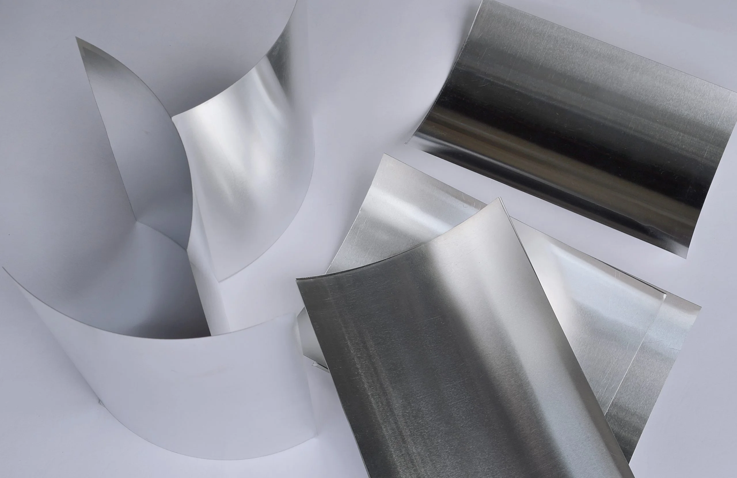
Thin sheet metal parts are components manufactured from low-thickness metal stock. There’s no universal definition of what qualifies as “thin,” but the parts discussed here are typically less than 3 mm thick. However, low-thickness metal parts are not defined by the manufacturing process used, but by their low material thickness relative to their overall geometry.
While it’s common to associate thin metal parts with sheet metal, the category is broader; it also includes precision-machined components that require thin walls or fine features. These parts can be produced using processes such as laser cutting, punching, bending, and CNC machining to achieve higher-precision features.
Because of their reduced thickness, thin metal parts behave differently from thicker components made using the same processes. They are more sensitive to the forces generated during manufacturing (heat, stress, etc.) and handling, which makes them more prone to warping, bending, tolerance variation, and damage during assembly.
This is why designing thin metal parts isn’t as simple as just making them as thin as possible. Manufacturers must consider how far a given process can reliably go while still maintaining structural integrity and precision. As parts approach low-thickness ranges, design constraints become more critical, and even small features require careful consideration.
How Thin Can Metal Be Manufactured?
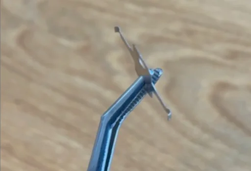
In terms of minimum sheet metal thickness, ultra-thin parts are achievable (think tin foil). Specialized manufacturers are capable of producing reliable ultra-thin metal parts as thin as 0.0003″ (≈7.6 microns) and as thick as 0.120″ (≈3 mm), with through-hole features as small as 0.0005″ (12.7 microns) for some materials, processes, and geometries. These parts are produced using Photochemical etching (PCE).
What Are the Use Cases for Thin Metal Parts?
Thin metal parts are popular in many industries because, when designed correctly, they can offer a strong balance between weight, cost (due to efficient material use), and formability. And thinner, lighter components may also improve performance.
Thin metal parts are found in the following applications:
- Consumer electronics (enclosures and shielding): EMI/RFI shielding covers, smartphone internal brackets, battery tabs, and thin aluminum or copper housings for consumer electronics.
- Aerospace and automotive (lightweight structural and functional components): heat shields, sensor brackets, battery enclosures for EVs, and lightweight panels used to reduce overall vehicle weight.
- Industrial and commercial equipment (mounting brackets and structural supports): control panel brackets, DIN rail mounts, equipment housings, and support frames for assemblies.
- Thermal management systems (heat shields and thermal barriers): exhaust heat shields, thermal interface plates, and thin stainless steel or aluminum barriers used to manage heat in engines or electronics.
- Medical and precision devices (miniaturized and high-accuracy components): surgical instrument components, diagnostic device housings, shims, and precision springs or clips used in small assemblies.
Across all these applications, the decision to use thin metal parts is usually driven by a few key goals:
- Reduce weight without compromising function
- Minimize material usage and cost
- Enable forming or shaping into complex geometries
- Support high-volume, repeatable manufacturing
Key Design Challenges for Thin Metal Parts
Warping and Deformation
Thin materials are highly sensitive to thermal and residual stresses. Processes like laser cutting introduce localized heat, which can cause distortion in larger or asymmetrical parts. Even after forming, residual stresses from bending or rolling can lead to unexpected warping over time. In production, this often shows up as parts that don’t sit flat, assemblies that require force to align, or dimensional variation that exceeds tolerance requirements.
Structural Weakness and Vibration
Reduced thickness directly impacts stiffness. Thin parts are more prone to flexing under load, which can lead to vibration issues or “oil-canning,” where flat surfaces visibly deform under small pressure changes. This becomes critical in applications like panels or enclosures, where even minor deflection can affect perceived quality or functional performance.
Tolerance Sensitivity
With thin metal parts, small dimensional deviations can have a disproportionate impact. A slight bend variation or thickness inconsistency can lead to misalignment during assembly, especially in stacked or multi-part systems.
Handling and Assembly Risks
Thin parts are more susceptible to damage during handling. Edges can bend, surfaces can deform, and fasteners can pull through if not properly designed. Assembly processes need to account for this. For example, applying torque to fasteners in thin sections can cause localized failure if reinforcement features are not included.
Design Guidelines for Thin Metal Parts
A few core design rules can significantly improve manufacturability and reduce risk.
- Select an appropriate minimum thickness based on the material and application. While thinner is often desirable, going too thin increases the risk of warping, handling damage, and instability.
- Bend radius should generally be greater than or equal to the material thickness to avoid cracking and excessive stress concentration.
- Hole diameters should generally not be smaller than the material thickness for punching operations, though laser cutting and etching may allow smaller features depending on material and thickness.
- Holes or features should be placed at least twice the material thickness away from the edges to maintain structural integrity.
- Avoid unnecessarily tight tolerances. Thin parts are inherently more variable, so tolerances should reflect realistic process capabilities.
The table below summarizes common guidelines, though exact limits depend on material, process, and geometry.
Sheet Metal Fabrication
| Feature / Rule | Sheet Metal Fabrication |
|---|---|
| Minimum thickness | ~0.5 mm (0.020″) typical; 0.08 mm possible with specialized processes |
| Minimum hole diameter | ≥ Material thickness (punching); smaller possible with laser cutting |
| Hole-to-edge distance | ≥ 2 × material thickness |
| Minimum bend radius | ≥ 1 × material thickness |
| Tolerance capability | ±0.1–0.2 mm typical (varies with thickness & size) |
| Key risk | Warping, springback, edge deformation |
Download our Sheet Metal Design Stack for more design and manufacturing guidelines
CNC Machining (Thin Features)
| Feature / Rule | CNC Machining (Thin Features) |
|---|---|
| Minimum thickness | ~0.8 mm (1/32″) recommended (depends on material & geometry) |
| Minimum hole diameter | ≥ 0.5 × tool diameter; typically ≥ 0.5–1.0 mm |
| Hole-to-edge distance | ≥ 1 × hole diameter (minimum) |
| Minimum bend radius | N/A |
| Tolerance capability | ±0.01–0.05 mm typical |
| Key risk | Vibration, deflection, tool chatter |
Photochemical Etching (PCE)
| Feature / Rule | Photochemical Etching (PCE) |
|---|---|
| Minimum thickness | 7.6 microns–3 mm (~0.0003″–0.125″); foil-gauge parts are PCE’s core strength |
| Minimum hole diameter | ≥ 1 × material thickness typical; as small as 0.0005″ on some ultra-thin foils |
| Hole-to-edge distance | ≥ 1 × material thickness typical |
| Minimum bend radius | N/A — parts etch flat; bends require a secondary forming step |
| Tolerance capability | ±10% of material thickness typical; tighter (~±0.001″) on ultra-thin foils |
| Key risk | Edge taper/undercut from isotropic etch; not suited to thick stock |
Material Selection for Thin Metal Parts
Material selection plays a critical role in how thin metal parts behave during both manufacturing and use. At lower thicknesses, materials respond differently to cutting, bending, and handling—strength isn’t the only factor. While many materials can be used, aluminum, steel, and stainless steel are the most common, each offering a different balance of properties.
Aluminum is lightweight, easy to form, and offers good corrosion resistance. This makes it ideal for enclosures and panels where weight matters, although it can be more challenging to laser cut due to reflectivity, especially at higher thicknesses.
Mild steel provides a high-strength, cost-effective option, but is harder to form at low thicknesses and requires coating to prevent corrosion. Stainless steel combines strength with excellent corrosion resistance, though it requires more force to form and can increase tooling wear and cost.
Materials like copper, brass, and titanium are typically reserved for specialized applications. Copper is highly ductile and ideal for electrical and thermal applications, but is soft and easily deformed. Brass offers good machinability and stability for precision thin metal fabrication, while titanium provides a high strength-to-weight ratio but comes with higher cost and manufacturing complexity.
As thickness decreases, these differences become more pronounced:
- Softer materials (like aluminum and copper) are easier to form but more prone to bending and handling damage.
- Stronger materials (such as steel and stainless steel) offer greater durability but require more force to form and are more prone to springback.
- Advanced materials (like titanium) offer high performance but significantly increase manufacturing complexity, cost, and lead time.
Thin Metal Component Fabrication Methods
Thin Sheet Metal Fabrication
Sheet metal fabrication is the most common method for producing custom thin metal parts. It includes processes such as laser cutting, punching, bending, and forming, which are well-suited for creating flat patterns and converting them into functional 3D geometries. These processes are highly efficient for both prototyping and high-volume production, especially when using standard material thicknesses and well-understood design rules.
For thin materials, careful control of cutting parameters and forming forces is critical to minimize heat distortion, edge deformation, and dimensional variation. Laser cutting is often preferred for thin parts due to its precision and flexibility, while punching can be more cost-effective at scale but introduces additional constraints on feature size and spacing. Bending and forming operations must also account for factors like springback and minimum bend radius, which become more pronounced as thickness decreases.
CNC Machining
CNC machining is typically used when higher precision or complex features are required. It allows for tight tolerances and detailed geometries, but thin sections can be difficult to machine due to vibration and deflection. The minimum recommended wall thickness for machining is 0.8 mm (1/32”) for metals and 1mm for plastics, as a common baseline, but thinner walls may be achievable depending on material, geometry, and machining strategy.
Photochemical Etching
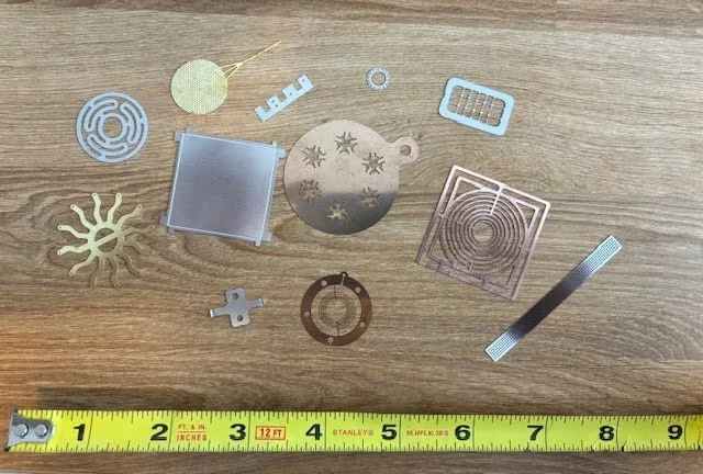
Photochemical etching (PCE), also called photochemical machining, is the process behind the thinnest parts in this guide, including foil-gauge components down to 0.0003″ (7.6 microns). Rather than cutting or stamping, PCE applies a photoresist mask to the metal, exposes the desired pattern, and dissolves the unmasked material in a chemical etchant. With no mechanical force, heat, or tooling contact, PCE produces burr-free, stress-free parts with no work hardening or heat-affected zone — an advantage for foils and geometries too delicate for laser cutting or punching.
PCE suits flat, two-dimensional geometries: EMI/RFI shielding, battery tabs and contacts, encoder discs, flexures, fuel cell plates, fine mesh, and lead frames. Tolerances typically run ±10% of material thickness (tighter on ultra-thin foils), and minimum feature size generally needs to equal material thickness, similar to punching. Because etching removes material isotropically, edges have a slight taper rather than the perpendicular wall of laser cutting or punching — worth accounting for in tight-fit designs. PCE doesn’t form 3D geometry on its own; parts needing bends are etched flat and formed as a secondary step.
Secondary Operations
Secondary processes such as finishing, coating, and hardware insertion may be necessary for final part performance and aesthetics. Finishing processes like anodizing or powder coating improve durability and appearance, but can introduce additional stresses or dimensional changes. Hardware insertion, such as PEM fasteners, must be carefully designed to avoid deformation or pull-through in thin materials.
Common Mistakes When Designing Thin Metal Parts
Designing thin metal parts comes with a unique set of challenges, and small oversights can cause costly issues in production.
- Specifying overly tight tolerances. While tighter tolerances may seem safer, they often increase cost, lead time, and the likelihood of rework. They should only be sought when adding real functional value.
- Risk of warping. Thin parts are highly sensitive to heat and residual stress, so flat components rarely remain perfectly flat after processes such as laser cutting or forming. Design with this in mind and specify realistic flatness tolerances to avoid unexpected deformation.
- Springback becomes more pronounced as thickness decreases and must be compensated for in bend design.
- Misunderstanding material thickness standards, such as gauge systems. Assuming incorrect thicknesses during design or sourcing can lead to mismatched parts, fit issues, and production delays.
- Designing without early DFM (Design for Manufacturability) input. A part may look correct in CAD, but without considering real manufacturing constraints, it can become difficult or expensive to produce at scale.
How to Optimize Thin Metal Parts for Manufacturability
Optimization starts with standardization. Using standard material thicknesses and well-established processes reduces complexity, improves consistency, and makes sourcing more predictable. Simplifying geometry wherever possible also plays a key role. Reducing unnecessary features helps minimize distortion, and ensuring that the part can be consistently formed within tolerances shortens manufacturing time.
Early validation through DFM feedback is one of the most effective ways to reduce risk. Identifying potential issues upfront allows teams to make adjustments before production, avoiding costly redesigns and delays. This means treating manufacturing as part of the design process from the beginning, rather than something to address later.
Prototyping and Sourcing Thin Metal Parts
Producing thin metal parts requires a balance of speed and accuracy. Rapid prototyping allows teams to validate design assumptions, but it must reflect real manufacturing conditions to be meaningful.
With the right approach and a manufacturing partner that provides DFM feedback early in the process, it’s possible to reduce iteration cycles, improve quality, and bring thin metal components to market faster and more efficiently. This approach simplifies sourcing, improves quality outcomes, and allows engineering teams to focus on design rather than logistics.
Platforms like Fictiv enable teams to move quickly from design to production by combining engineering support with access to a global network of manufacturing partners. Fictiv helps teams design and manufacture thin metal parts with confidence by providing DFM feedback tailored to low-thickness geometries, access to specialized fabrication capabilities, and a global supply network for reliable production.
Upload your CAD file to get started
Talk to a Fictiv expert about your project, or upload your parts to start a free quote.
FAQs About Thin Metal Parts
What is considered a thin metal part?
Thin metal parts are components with low material thickness relative to their overall geometry, typically below 1–3 mm. At these thicknesses, manufacturing constraints such as warping, stress, and handling become more significant and must be considered during design.
What is the minimum thickness for sheet metal?
The minimum thickness for standard sheet metal fabrication is typically around 0.5 mm (0.020″), depending on the material and process. Thinner materials—down to ~0.08 mm or less—are possible using specialized processes such as photo chemical etching (PCE) or foil-based fabrication, but may involve additional cost and design constraints.
What is photo chemical etching, and when is it used for thin metal parts?
Photo chemical etching (PCE), also called photochemical machining, uses a photoresist mask and a chemical etchant to dissolve metal into a precise pattern, without heat or mechanical force. It’s used for foil-gauge and ultra-thin parts—down to about 0.0003″ (7.6 microns)—such as EMI shielding, battery contacts, encoder discs, and flexures, where laser cutting or punching would introduce too much stress or distortion.
What is the minimum hole size in thin sheet metal?
For punched sheet metal parts, the minimum hole diameter is typically equal to or greater than the material thickness. Laser cutting and photo chemical etching may allow smaller features, but this depends on the material and thickness and may impact edge quality and tolerances.
What are the main challenges when designing thin metal parts?
The main challenges include warping from heat and residual stress, reduced stiffness and increased vibration, sensitivity to tolerances, and a higher risk of damage during handling and assembly. These factors require careful consideration of material selection, geometry, and manufacturing processes.