




Time to read: 14 min
A robot arm can assemble cleanly, pass every bench check, and still miss its target in the field. The problem often starts with the structural links, or the rigid segments that connect one joint to the next.
Link design problems tend to fall into three groups:
- A link that deflects under load and degrades tool center point (TCP) accuracy
- A link heavier than it needs to be because the pocketing (material removed from low-stress regions to save weight) was never optimized
- A link without finish built into the design, so anodize growth pushes bores out of tolerance and, on thin, highly stressed sections, hard anodize can reduce fatigue life
The first two problems trace back to one tradeoff. Every gram in a link has to be carried by every joint upstream of it, so a lighter link means less load on the motors and room for more payload or speed. But material is also what keeps a link stiff. Remove too much and the link flexes, so the TCP, the spot where the tool does its work, stops landing where the controller expects. The third problem, finish, works differently: it changes a part’s dimensions after it has been machined.
All three are decided on the drawing before the part reaches the production floor.
This article walks through the decisions that determine how a link performs, including materials, pocketing rules, joint interface tolerances, and finishes. It builds on our overview of robotic arm components manufacturing within our wider robotics hardware manufacturing guide framework.

Robotic Arm With Structural Links
Robotic Arm Structural Components: Links and Frames
Structural links are rigid segments between joints in a robot arm that contribute to arm reach, weight distribution, and overall stiffness. Links run between the actuator housings that contain the motors and gearboxes. The end-of-arm tooling, which handles the workpiece, mounts at the far end of the last link.
A frame differs from a link in what it does. A link moves with the arm and carries load from one joint to the next. A frame holds joints and loads in fixed positions relative to each other. Three variants cover most designs:
- Base frames: mount the first joint to the base, giving the arm a rigid foundation.
- Structural links: connect one joint to the next.
- Wrist links: connect the final joint to the tooling interface.
Link geometry is almost always custom. Length, cross section, and interface pattern follow the robot’s kinematic design, so no catalog part matches a given arm’s reach and mounting requirements. Many of the same principles carry over to humanoid robotics manufacturing.
This guide focuses on CNC-machined links, which are typical for prototypes, low volumes, and high-precision arms. Production arms often use die casting, or sheet metal and extrusions for lighter-duty designs. Cast and fabricated links still typically need CNC machining on the features that control accuracy, such as bearing bores, flange faces, and datum surfaces.
With link length and interfaces set by the robot’s kinematics, material is the next major decision.

Material Selection for Robotic Structural Links
Robotic structural links are commonly machined from these materials, depending on whether the limiting factor is strength, stiffness, or weight. Pick the wrong material and a link can be too flexible, too heavy, or too expensive.
6061-T6 Aluminum
6061 is the default material for robotic arm structural links for good reason. It machines cleanly, costs less than the other options below, and takes anodizing well for corrosion protection and color coding. Its Young’s modulus of 69 GPa is moderate, about one third that of steel, which is enough for most links when the geometry is designed well.
7075-T6 Aluminum
7075 earns its place when the strength of 6061 is not sufficient for the application. A common use case is shoulder and upper-arm links carrying full-arm payload at maximum reach, or links under high dynamic loads. Typical yield strength is roughly 75% higher at a similar weight (about 480 MPa, versus 270 MPa for 6061-T6). Stiffness, though, is nearly identical, so 7075 does nothing for a link limited by deflection instead of strength. It also costs more than 6061 and welds poorly, so design for fastened assembly.
Carbon Fiber Reinforced Polymer (CFRP)
CFRP is chosen when the application’s requirements exceed aluminum’s stiffness-to-weight ratio. Think long-reach arms, high-speed applications, and humanoid limbs where every gram counts. Along the fiber axis, unidirectional CFRP delivers roughly three to four times the specific stiffness of aluminum, with published robot manipulator studies reporting longitudinal moduli near 142 GPa, compared to just 69 GPa for aluminum. Across the fibers, CFRP is far weaker, so fiber orientation matters.
CFRP also changes how a link is made. Rather than cutting the link from solid billet, manufacturers typically bond a composite tube to machined aluminum end fittings. The tube can be a standard pultruded or roll-wrapped stock size, or a custom composite layup with fiber angles, wall thickness, and length tuned to the link’s stiffness and torsion requirements. The fittings are the part designed for CNC machining, and the tube is specified separately.
Titanium (Ti-6Al-4V)
Titanium suits links that need more strength than aluminum at less weight than steel, which is mostly applicable in aerospace and defense programs. Its stiffness-to-weight is similar to aluminum’s, so it offers minimal advantage for a link limited by deflection. It also costs significantly more to machine, so reserve it for programs where the performance requirements justify the premium.
Common Robotic Arm Structural Link Materials Table
| Material | Density (g/cm³) | Young’s modulus (GPa) | Best for | Key limitation |
| 6061-T6 aluminum | 2.70 | 69 | Most robot links, standard applications | Stiffness-to-weight limit on long-reach arms |
| 7075-T6 aluminum | 2.81 | 72 | High-load shoulder links, dynamic applications | Poor weldability, higher cost |
| CFRP (unidirectional) | 1.55 | 130 to 180 axial | Long reach, humanoid, weight-critical links | End fitting design, anisotropic properties |
| Ti-6Al-4V | 4.43 | 114 | Aerospace, defense, extreme load applications | High machining cost |
Material sets the link’s stiffness and weight. Next comes a practical question: which parts of the arm need a custom design and which don’t?
Designing Custom Links Around Catalog Components
Not every part in a robotic arm assembly needs a custom drawing.
Structural link bodies are typically custom manufactured. Length, cross section, interface geometry, and pocketing pattern follow the robot’s kinematics. On top of that, aluminum stock is inexpensive enough that it rarely makes sense to force a standard profile to fit.
The parts a link connects to are different. Joint modules such as strain wave gears, planetary gearboxes, and frameless motor kits ship with published specifications, as do the catalog components that sit around them: gears, actuators, bearings, shaft collars, couplings, guide rails, and fasteners. They sit outside the link design, but their bore sizes and mounting patterns shape it, so the link is designed around them and not the reverse.
Tracking custom and catalog parts in a single bill of materials (BOM) and sourcing them through one partner helps reduce schedule mismatches, since the two rarely share the same lead time.
With the catalog parts defined, the link’s own geometry is next—starting with where to remove weight.
Pocketing: Removing Weight While Maintaining Stiffness
Excess weight compromises arm performance, especially near the wrist. Mass there is carried at the longest lever arm, so trimming it lowers the torque demand on every upstream joint.
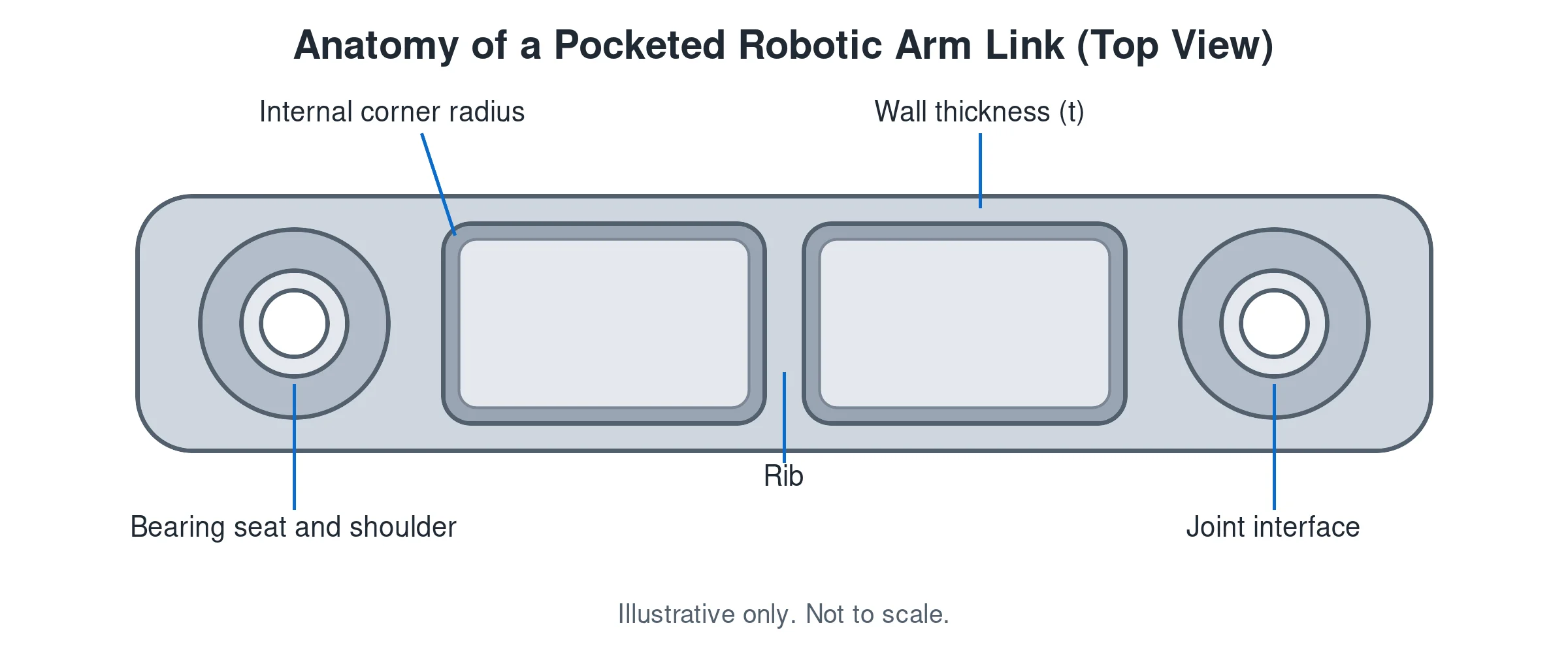
Pocketing, which cuts material out of low-stress regions of a link, is a primary DFM decision on a structural link. It removes weight while relying on ribs to preserve stiffness. Cast links remove weight with internal cores and ribs, while machined links use pockets. The rules below apply to machined links.
Wall Thickness
A minimum wall thickness of 2.5 to 3.0 mm is common for pocketed aluminum links. Thinner walls are possible with careful toolpath planning to avoid chatter and tool deflection. Treat these numbers as a starting point, since the real limit depends on wall height, pocket depth, material, and tooling. Walls at least one-eighth as thick as their height are recommended. Thinner walls save weight, but you risk failure points and increased machining costs.
Corner Radii
Use generous radii matched to standard end mills. Keep pockets shallow if possible, but use a larger radius for deeper pockets, with a size at least a quarter of the pocket’s depth. Sharp internal corners force smaller tools, extra passes, and longer cycle times with no weight benefit.
Ribs
Longitudinal ribs restore the bending stiffness that pocketing removes, while transverse ribs keep thin walls from buckling and diagonal ribs add torsional stiffness. Ribs that are narrow relative to their height tend to chatter during machining, so make sure they are thick enough to stay rigid under the cutter.
Machining From Both Faces
Machining pockets from both faces avoids the depth limit of single-sided tooling, so more material can come out than with blind pockets cut from one face. This requires a flip setup, which most machined links need anyway. Reference holes and flat surfaces usable in both setups keep positional accuracy intact.
Check out our CNC Machining Design Guide for more tips.
Pockets and ribs control the link’s weight and stiffness, but accuracy is set where the link meets everything else: at the joints.
Joint Interface Geometric Dimensioning and Tolerancing
The geometric dimensioning and tolerancing (GD&T) on a link determines how accurately it positions the joints at either end. A link can assemble without trouble and still degrade TCP accuracy in service if its joint interface features are out of position or out of flat. A tolerance stackup across the arm’s joints shows whether the link is the source. Calibration only goes so far. Fixed deflection can be calibrated out. Deflection that changes with pose, load, or vibration can’t be calibrated out, and it compromises positional accuracy in any task that depends on it.
Four features matter most:
- Bearing seats and shaft interfaces: Use ISO H7 bores for typical bearing outer-ring seats, or H6 where positional requirements are tighter. Choose the mating tolerance to get the intended engineering fit (clearance, transition, or interference). Specify Ra 0.8 μm or better on bearing surfaces. See Surface Finishing for anodize allowances.
- Flange face flatness: 0.05 mm or better is typical on critical faces that mount motors, gearboxes, and joint modules, ideally milled in a single setup.
- Axis alignment: Where a link has bearing interfaces at both ends on the same axis, such as an inline roll joint, misalignment between the bores degrades TCP accuracy. Control it with a position tolerance to a datum axis per ASME Y14.5, and verify with a runout check if needed. Common starting values are 0.05 mm for standard collaborative robot applications and 0.02 mm for precision work, but confirm them against the arm’s error budget. Machine both bores in a single setup to hold a tighter target, using five-axis machining when the bores sit on different faces.
- Threaded interfaces: Use a single thread system per part (UNC/UNF or metric) and standard sizes, with at least 1.5 times the nominal diameter of thread engagement in aluminum. Use wire thread inserts (such as Helicoil) at locations that will be fastened and unfastened often.
Even perfectly toleranced features can drift out of spec after finishing. Anodizing adds material, and it’s easy to forget until the bores no longer fit.
Surface Finishing for Robotic Links: Make Sure Your Dimensions Account for Anodizing
Robotic arm links are often finished for corrosion and wear protection, and the right finish depends on the material and the environment the link will see.
Anodizing changes part dimensions, so plan for it before the drawing is released. For bearing bores and other tight-tolerance features, there are a few options. You can machine to a compensated size so the feature lands on target after anodizing, leave extra stock and finish-machine after anodizing, or mask the feature before anodizing so it stays uncoated.
Type II Anodize
Type II anodize per MIL-PRF-8625 (the current designation of the older MIL-A-8625 specification) is the standard finish for most robot links. It adds corrosion and wear resistance and supports color coding and identification. It also changes part dimensions. Roughly half of the coating grows outward from the original surface, so a typical Type II coating can add about 0.003 to 0.010 mm per surface. On a bore, that shrinks the diameter by about twice that amount.
Type III Hard Anodize
Type III hard anodize is best for links that are exposed to abrasion, sliding contact, or harsh environments. A typical 0.05 mm coating grows about 0.025 mm per surface, so build an allowance for that growth into the machining dimensions from the start. Growth scales with coating thickness, so check the thickness callout on the drawing and size the allowance to match it. Hard anodize can also lower fatigue strength, which matters on thin, highly stressed sections.
Worked example: A bearing seat is machined to 40 mm H7 (+0.025/0 mm) and finished with a 0.05 mm Type III coating. The coating shrinks the bore diameter by about 0.05 mm, from 40.000–40.025 mm to roughly 39.950–39.975 mm, so a bearing with a 40 mm outer diameter no longer slides in. Forcing it risks distorting the outer ring and adding preload and friction. Masking the seat before anodizing, or finish-machining it afterward, avoids the problem.
CFRP Surfaces
CFRP links are typically sealed with a clear coat or left as manufactured. Skip paint unless identification requires it, since paint adds weight and can hide surface damage. Prepare aluminum end fittings for bonding per the adhesive manufacturer’s instructions. Sealed anodize bonds poorly, so specify unsealed or phosphoric acid anodize on bond areas.
Getting Structural Links Built Right
Deflection, excess weight, and out-of-tolerance bores all come back to the same place: design decisions made on the link’s drawing, before anyone cuts metal. Match the material to what limits the link, pocket with ribs in mind as needed, control the joint interfaces, and build finish growth into the dimensions. Do that, and all three problems stay off the production floor.
Fictiv’s manufacturing network supports robotics programs with CNC machining, casting, anodizing, and precision assembly.
Upload your part design for a quote with DFM feedback, and correct design and dimensioning problems before they reach the manufacturing floor.
Talk to a Fictiv expert about your project, or upload your parts to start a free quote.
FAQs About Robotic Arm Structural Links
What are robotic arm structural links?
Structural links are the rigid segments that connect one joint of a robot arm to the next. They set reach, contribute to weight distribution and stiffness, and carry load between joints. Their length and interface pattern follow the robot’s kinematic design, so they are almost always custom-designed.
What is the best material for robotic arm structural links?
6061-T6 aluminum is the usual default because it machines cleanly, costs less than the alternatives, and anodizes well. 7075-T6 suits links limited by strength. CFRP tubes with machined aluminum end fittings suit long-reach or weight-critical arms. Titanium suits high-strength programs but costs significantly more to machine.
Is 7075 aluminum stiffer than 6061 for robot links?
No. Their Young’s moduli are nearly identical, about 72 GPa for 7075 and 69 GPa for 6061. 7075 has roughly 75% higher yield strength, so it helps links limited by strength or dynamic loads, but not links limited by deflection. Deflection-limited links need better geometry or CFRP.
How does anodizing affect robot link tolerances?
Anodize grows outward from the surface, and a bore’s diameter shrinks by about the total coating thickness. A 0.05 mm Type III coating shrinks a bore by about 0.05 mm, which can exceed a bearing seat’s tolerance. Options are machining to a compensated size, finish-machining after anodizing, or masking the feature beforehand.
Can robotic arm structural links be cast instead of machined?
Yes. CNC machining is typical for prototypes, low volumes, and high-precision arms, while production arms often use casting, or sheet metal and extrusions for lighter-duty designs. Cast and fabricated links still typically need CNC machining on bearing bores, flange faces, and datum surfaces, which control accuracy.