





Time to read: 13 min
At scale, cycle time is one of the most direct levers on injection molding costs. It affects both cost per part and maximum throughput, so any design or tooling decision that changes cycle time also changes piece price—at every production volume. For this reason, design engineers and manufacturing or tooling engineers must strike a balance to achieve the highest yield per dollar while avoiding common defects that affect part quality.
What Is Injection Molding Cycle Time?
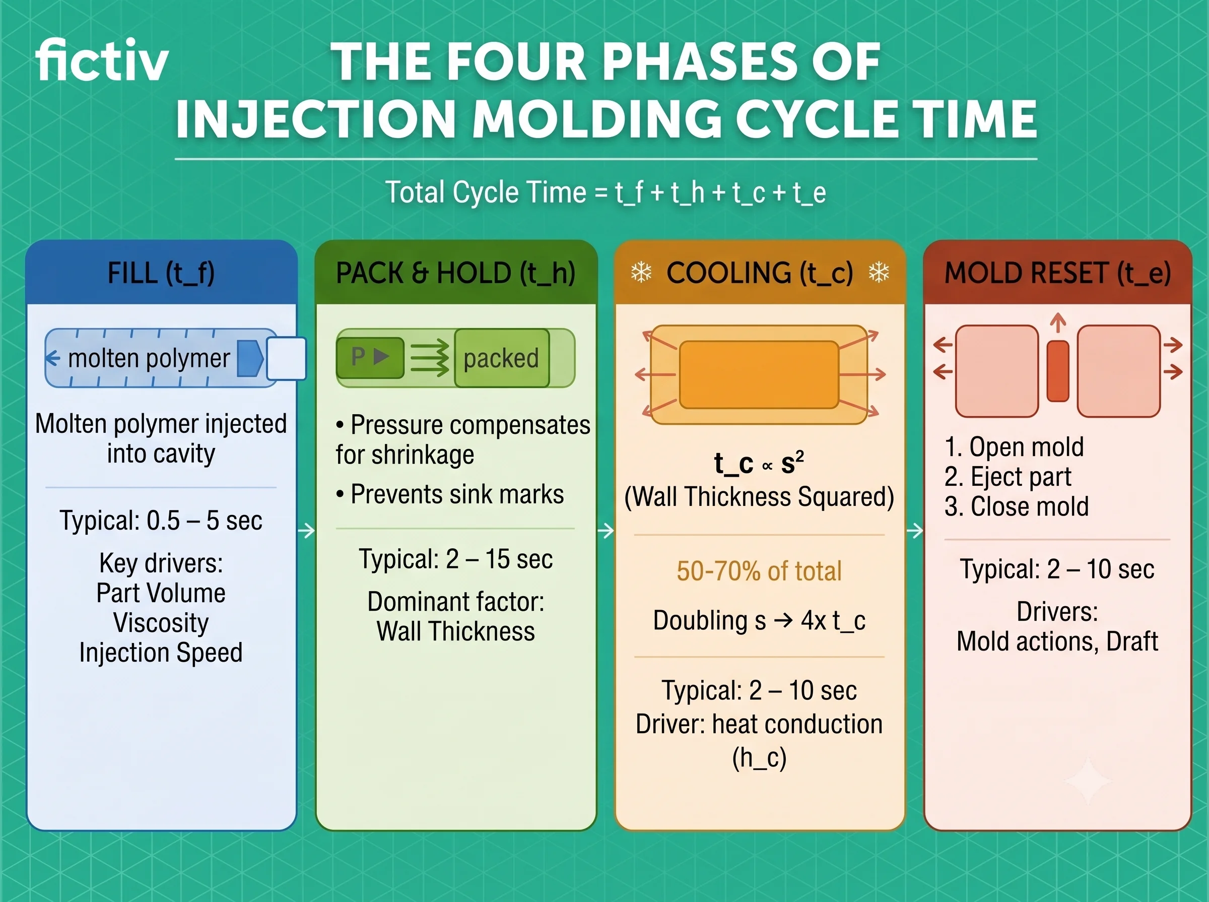
Injection molding cycle time is the total elapsed time from the start of one injection cycle to the start of the next. It is the sum of the durations of four sequential phases: fill, pack and hold, cooling, and mold reset (open, eject, close). Cycle time directly determines cost per part and annual production capacity on a given press.
The total injection molding cycle time is calculated as:
tt = tf + th + tc + te
Where:
- tt = total cycle time
- tf = fill time
- th = pack and hold time
- tc = cooling time
- te = mold open, eject, and close time
Typical cycle times range from 2 seconds for smaller thin-walled parts to over 60 seconds for thick structural housings, depending on geometry, material, and tooling. A general breakdown by part type is as follows:
- Thin-wall, high-volume parts (packaging, closures): 2–10 seconds
- General engineering parts (enclosures, brackets, housings): 15–45 seconds
- Thick structural or large parts (automotive, industrial): 60–120+ seconds
The Four Phases of Injection Molding Cycle Time
Injection / Fill Phase
Molten polymer is injected into the mold cavity under pressure. The injection unit’s reciprocating screw acts as a plunger, pushing material forward through the sprue (the main feed channel), runner system, and gate(s) until the cavity is full. Fill typically takes 0.5-5 seconds. Key drivers of fill time are part volume, polymer viscosity, injection speed/pressure, and gate size/location.
Pack and Hold Phase
Once the cavity is filled, the screw maintains pressure on the melt to compensate for volumetric shrinkage as the material cools and densifies. Without adequate hold pressure and time, parts can develop sink marks over thick sections or end up undersized. Pack and hold typically requires 2 to 15 seconds.
Wall thickness is the dominant factor: thicker sections shrink more and require longer hold times. Hold pressure may also need adjustment alongside hold time, particularly for semi-crystalline polymers such as polypropylene and nylon, which generally shrink more than amorphous materials such as ABS or polycarbonate.
Cooling Phase
Cooling typically accounts for 50 to 70% of total cycle time. Cooling time does not scale linearly with wall thickness. It scales with the square of wall thickness:
tc ≈ (s² / (π² × a)) × ln((4/π) × (Ti − Tw) / (Te − Tw))
Where:
- tc = cooling time
- s = wall thickness (mm)
- a = thermal diffusivity of the polymer (mm²/s)
- Ti = melt temperature (°C)
- Tw = coolant temperature (°C)
- Te = ejection temperature (°C)
This equation is a one-dimensional approximation for a uniform, planar wall section. It becomes less accurate for cylindrical features, thick bosses, and complex 3D geometries, where multi-directional heat transfer dominates. Use it for directional comparison and early-stage estimation, not final process specification.
Example: For a 3 mm ABS wall section (a ≈ 0.13 mm²/s), with a melt temperature of 230°C, coolant at 30°C, and an ejection temperature of 85°C, the estimated cooling time is approximately 18–22 seconds—consistent with observed cycle times for general-purpose ABS enclosures.
The practical consequence is that doubling wall thickness roughly quadruples cooling time. This quadratic relationship makes wall thickness reduction the most impactful design lever for shortening cycle time.
Mold Open / Eject / Close Phase
The mold opens, the ejector system pushes the part free, and the mold closes and clamps shut again in preparation for the next shot. This phase typically takes 2 to 10 seconds but can be longer on tools with multiple side actions, complex ejector systems, or parts with insufficient draft.
Mold opening with part ejection
What Factors Affect Injection Molding Cycle Time?
Part Design
Wall thickness has the largest influence on cycle time of any design variable. Because cooling time scales with the square of thickness, even modest reductions produce significant improvements. A 20% reduction in wall thickness can cut cooling time by roughly 35%.
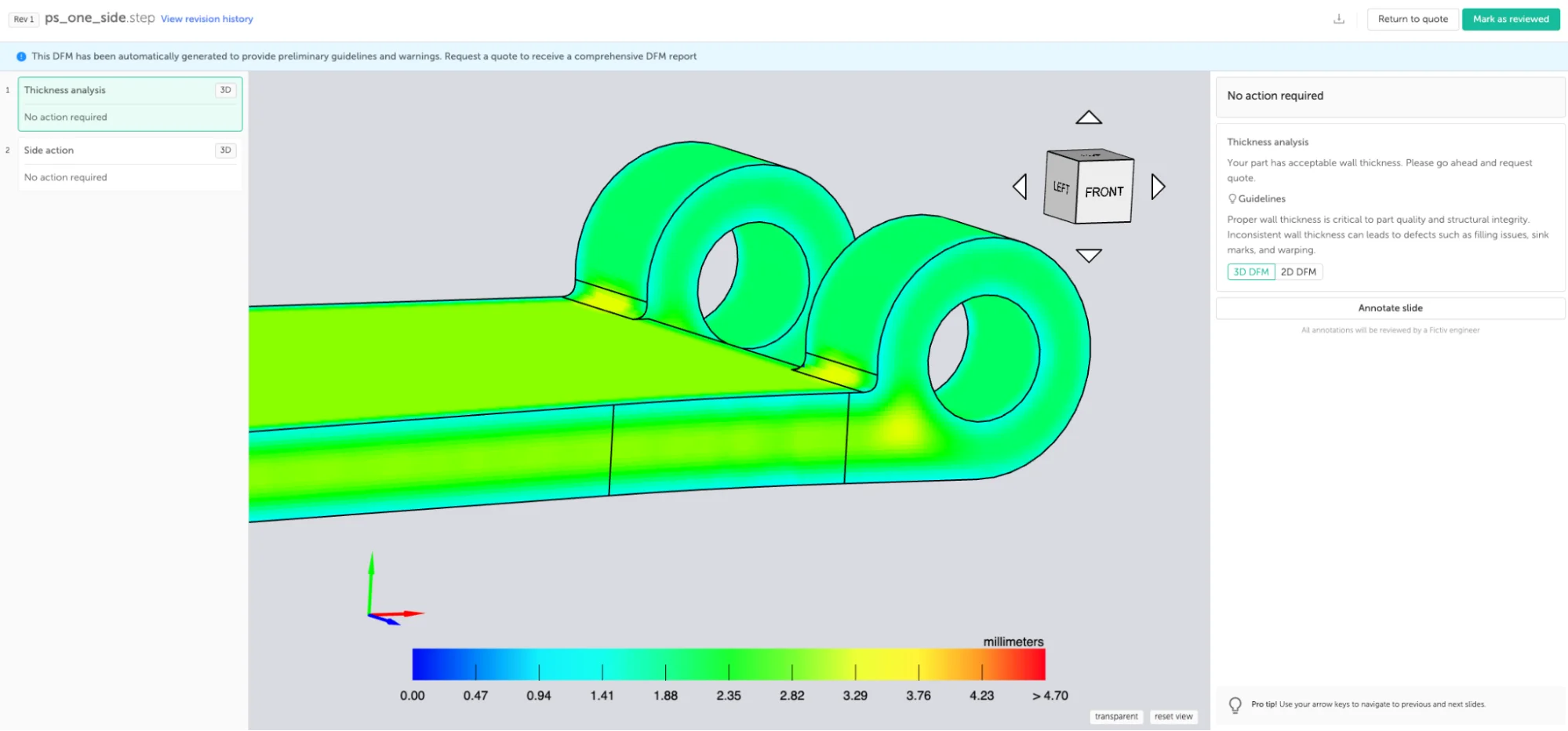
Wall thickness uniformity matters for the same reason. Non-uniform sections, at bosses, ribs, and transitions, retain heat longer than surrounding walls. The entire cycle waits on the slowest-cooling feature, regardless of how quickly the rest of the part cools.
Where possible, eliminating undercuts reduces tool complexity and reset time. This can be achieved by reorienting the part relative to the mold parting line, replacing closed pockets with open slots that the mold can clear without lateral movement, or revising feature geometry to remove the locking condition entirely.
Learn more tips on optimal part design with Fictiv’s Injection Molding Design Guide.
Material Selection
Thermal diffusivity determines how quickly a polymer transfers heat to the mold. Semi-crystalline polymers (PP, PA, POM) cool more slowly than amorphous materials (ABS, PC, PMMA) at equivalent wall thickness because they release latent heat as their molecular structure reorganizes during solidification.
Try Materials.AI for assisted material selection for injection molding, or reference our Injection Molding Material Selection Guide.
Tooling Design
Mold material determines the rate of heat transfer from the solidifying part into the tool. Aluminum has a thermal conductivity roughly four times higher than P20 steel, which shortens cooling time. However, aluminum tools typically support only 10,000 to 100,000 shots, so at higher volumes steel tooling is generally preferred, as wear life becomes the more important constraint.
Cooling channel placement within the mold is the other primary tooling variable. Channels too far from the cavity surface extract heat slowly; channels too close can weaken the mold or cause uneven cooling. For conventional round channels, a commonly used guideline is center-to-center spacing of approximately three times the channel diameter at a depth of 1.5 times the channel diameter from the cavity surface.
Conformal cooling channels follow the part contour rather than running straight through the mold block, maintaining more consistent proximity to the cavity wall. They can reduce cooling time by 20 to 40% compared to conventionally drilled channels on complex geometries.
Gate type and location affect both fill time and the minimum achievable hold time, since hold pressure must be maintained until the gate freezes and seals the cavity. A larger gate cross-section takes longer to freeze, extending hold time; a smaller gate freezes faster but increases fill pressure. Gate location also determines fill path length and weld line placement, both of which influence the pressure and time required to complete the shot.
Hot runner systems eliminate the sprue and runner from the cycle entirely, removing that thermal mass from the cooling calculation and shortening overall cycle time. They are standard practice at moderate to high production volumes and become increasingly cost-justified as annual shot count grows, though they add tooling complexity and require careful thermal balancing in multi-cavity tools.
Summary of Key Cycle Time Variables
| Process / Design Variable | Impact on Cycle Time | Primary Owner |
| Nominal wall thickness | Very high (quadratic relationship) | Part designer |
| Wall section uniformity | High (non-uniform sections delay cooling) | Part designer |
| Conformal cooling channels | High (20 to 40% reduction possible) | Tooling engineer |
| Mold material selection | Medium to high | Tooling / sourcing |
| Polymer material selection | Medium | Part designer |
| Mold temperature setpoints | Medium | Process engineer |
| Side actions / lifters | Low to medium | Part designer |
| Gate design (type and location) | Medium to high (affects hold and fill time) | Part designer / tooling engineer |
| Hot runner system | Medium to high | Tooling engineer |
| Screw recovery time | Low to medium (when plasticating time exceeds cooling phase) | Process engineer |
How to Reduce Injection Molding Cycle Time
Design-Stage Reductions
Minimize and standardize wall thickness. A 20% reduction can cut cooling time by approximately 35% and also reduce material use.
Avoid isolated thick cross-sections. Bosses, ribs, and gussets are generally designed at 40 to 60% of nominal wall thickness to prevent them from becoming heat-retaining hot spots.
Eliminate unnecessary undercuts where the added mold complexity outweighs the benefits. A revised parting line, an open slot, or a post-mold assembly operation may each be viable, but each involves tradeoffs in tooling cost, part count, and assembly time that should be evaluated for the specific application.
Design for adequate draft. A minimum of 1 to 3 degrees is standard on most surfaces; textured surfaces typically require more.
For tolerance implications, refer to Fictiv’s Injection Molding Tolerances article.
Tooling and Process Reductions
Optimize cooling channel layout. Position channels approximately 1.5 times the channel diameter from the cavity surface, with consistent channel-to-channel spacing, and confirm coolant flow is turbulent rather than laminar.
Consider conformal cooling for complex geometries. Conformal cooling channels are curved channels in mold inserts that follow the part surface contour, maintaining more uniform proximity to the cavity wall than straight-drilled channels. The inserts are typically produced through additive manufacturing. Cooling time reductions of 20 to 40% are possible depending on geometry.
Evaluate aluminum tooling where faster heat extraction is a priority and production volumes are limited. Aluminum’s thermal conductivity is roughly four times higher than P20 steel. Mold life is more limited, though, typically 10,000 to 100,000 shots, so the decision involves balancing thermal performance, tooling cost, and expected production volume.
Use multi-cavity tooling at appropriate production volumes. Multiple cavities increase output per cycle without changing cycle time. The tradeoff is higher tooling cost and complexity, which increases maintenance requirements and the consequences of a tool failure.
Review hold time settings. The goal of the hold phase is to maintain pressure until the gate solidifies, sealing the cavity against backflow. Hold time is often set conservatively and can sometimes be reduced incrementally without affecting part weight, dimensions, or surface quality.
Select gate type and location with freeze time in mind. Faster-freezing gate geometries reduce the minimum viable hold time and can trim several seconds from the cycle without any tooling rework after the tool is cut, making this one of the lowest-cost cycle time decisions available at the design stage.
Cycle Time vs. Part Quality
Process parameters can be adjusted to reduce cycle time, but each involves quality tradeoffs. Lowering mold temperature speeds cooling but can degrade surface finish, reduce weld line strength, and increase residual stress near the gate.
Reducing cooling time below what the part requires risks ejecting it before it has sufficient rigidity, causing warpage. Increasing injection speed shortens fill time but can cause shear degradation in sensitive polymers. In each case, the practical minimum is set by the first quality problem that appears.
Screw recovery—the time required to melt and meter the next shot—usually runs in parallel with cooling and adds nothing to total cycle time. On fast cycles or with large shot weights, plasticating can take longer than the cooling phase. When that happens, screw recovery becomes the cycle-limiting step, and further cooling optimization yields no benefit.
Where quality constraints limit process adjustments, the more effective path is design-stage changes made before tooling is committed, primarily wall thickness reduction. Ejection speed can also be increased to trim reset time, provided draft angles are sufficient to prevent the part from dragging against the mold wall, which can cause surface marking or damage to the mold gate.
How Fictiv Supports Cycle Time Optimization
Cycle time optimization is most effective when addressed before tooling is released for build. Fictiv’s platform supports this through automated DFM (Design for Manufacturability) feedback that flags wall thickness issues, non-uniform sections, and problematic undercuts early in the design process.
Moldflow analysis simulates fill, pack, and cooling behavior before tooling is cut. Vetted tooling partners include suppliers with conformal cooling and aluminum or soft steel tooling capabilities. For programs moving from prototype to production, Fictiv also supports tooling strategies for scaling up to multi-cavity production so that initial tooling decisions align with production economics over the longer term.
Want to optimize your part design for faster cycle times? Get a free quote and DFM review from Fictiv.
Talk to a Fictiv expert about your project, or upload your parts to start a free quote.
FAQs About Injection Molding Cycle Time
What is a typical injection molding cycle time?
Injection molding cycle times typically range from around 2 seconds for small, thin-walled parts to over 60 seconds for thick structural housings. Most general-purpose parts fall somewhere between 10 and 40 seconds. The exact cycle time depends on wall thickness, part geometry, material, and tooling — with cooling time accounting for 50 to 70% of the total in most cases.
What is the biggest factor affecting injection molding cycle time?
Wall thickness is the single largest design variable affecting cycle time. Cooling time — which typically makes up 50 to 70% of the total cycle — scales with the square of wall thickness, meaning that doubling wall thickness roughly quadruples cooling time. A 20% reduction in wall thickness can cut cooling time by approximately 35%, making wall thickness reduction the highest-leverage design change available before tooling is committed.
How is injection molding cycle time calculated?
Total cycle time is the sum of four sequential phases: fill time (tf), pack and hold time (th), cooling time (tc), and mold reset time (te). The formula is: tt = tf + th + tc + te. Cooling time can be estimated using the equation tc ≈ (s² / (π² × a)) × ln((4/π) × (Ti − Tw) / (Te − Tw)), where s is wall thickness, a is the thermal diffusivity of the polymer, Ti is melt temperature, Tw is coolant temperature, and Te is ejection temperature. This approximation is most reliable for uniform, planar wall sections.
How can I reduce injection molding cycle time without affecting part quality?
The most effective reductions come from design-stage decisions made before tooling is built. Minimizing and standardizing wall thickness has the largest impact, since cooling time scales with thickness squared. Avoiding isolated thick sections at bosses and ribs, eliminating unnecessary undercuts, and designing adequate draft angles all reduce cycle time without quality tradeoffs. On the tooling side, optimized cooling channel placement, conformal cooling channels, and aluminum tooling for lower-volume runs can reduce cooling time by 20 to 40%. Process adjustments such as reducing hold time or increasing ejection speed offer smaller gains and must be validated against part quality metrics.
Why does cooling take so long in injection molding?
Cooling dominates cycle time because heat must conduct out of the polymer through the mold wall and into the coolant — a process governed by the thermal properties of the material, the mold temperature, and critically, the wall thickness of the part. Because cooling time scales with the square of wall thickness rather than linearly, even modest increases in section thickness have a disproportionate effect. Semi-crystalline polymers such as polypropylene and nylon cool more slowly than amorphous materials like ABS or polycarbonate because they release additional latent heat as their molecular structure reorganizes during solidification.